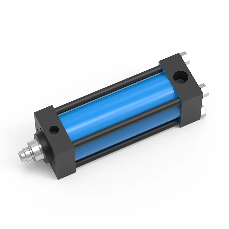
Pneumohydraulic Drive (with Separate Working Cylinder), HZ Series
- Operating pressure ≤6bar
- Pressing force 2-2000kN
- Force stroke 5-52mm
- Total stroke 100/200/250mm
The pneumohydraulic drive combines the advantages of compressed air and hydraulic systems, integrating the high-speed motion of the pneumatic cylinder with the high intensity of hydraulic systems. The pneumohydraulic drive is a specially designed cylinder that requires an intensifier to drive low-pressure oil for the rapid advance stroke. Once in position, the intensifier provides high-pressure oil to perform the work.
Operating Parameters
| Model | Cylinder bore (mm) | Pressing Force Output (kN, at 250 bar input oil pressure ) | Approach Stroke Force (kg, at 6 bar air pressure) | Return Stroke Force (kg, at 6 bar air pressure) | Oil Consumption per 1mm Stroke (V, CC) | Approach Stroke Oil Loss (V1, cCC, per 50mm) | Hose Expansion/Loss (V2, CC, per 100mm of hose length) | Hydraulic Hose Specification |
| | 50.00 | 48.00 | 115.00 | 90.00 | 2.00 | 2.20 | 0.50 | 3/8" Two-Layer Wire Spiral High-Pressure Hose |
| | 63.00 | 76.00 | 185.00 | 130.00 | 3.10 | 3.40 | 0.60 | 3/8" Two-Layer Wire Spiral High-Pressure Hose |
| | 80.00 | 108.00 | 260.00 | 210.00 | 4.40 | 4.90 | 0.60 | 1/2" Four-Layer Wire Spiral High-Pressure Hose |
| | 100.00 | 192.00 | 465.00 | 350.00 | 7.90 | 8.60 | 0.70 | 1/2" Four-Layer Wire Spiral High-Pressure Hose |
| | 125.00 | 300.00 | 720.00 | 580.00 | 12.30 | 13.50 | 0.70 | 1/2" Four-Layer Wire Spiral High-Pressure Hose |
| | 160.00 | 492.00 | 1182.00 | 887.00 | 20.10 | 22.00 | 0.70 | 1" Four-Layer Wire Spiral High-Pressure Hose |
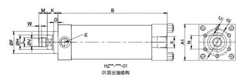
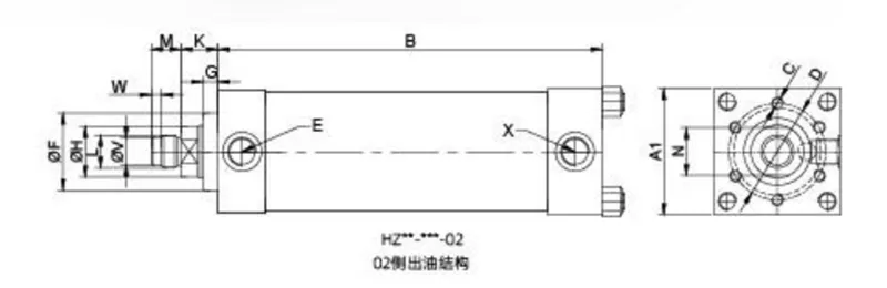
Cylinder Stroke Parameters
| Model | A1 | B (based on stroke change) | C | D | E | F (f7) | G | H | K | L | M | N | V | W | X |
| | 67 | 240+(stroke-100) | 6-M8×15 | 54 | G3/8 | 40 | 10 | 25 | 25 | M16×1.5 | 22 | 19 | 12 | 7 | G1/2 |
| | 85 | 255+(stroke-100) | 6-M8×15 | 65 | G3/8 | 52 | 10 | 35 | 25 | M22×2 | 20 | 17 | 18 | 7 | G3/4 |
| | 112 | 265+(stroke-100) | 6-M10×20 | 88 | G1/2 | 70 | 10 | 45 | 35 | M30×2 | 25 | 36 | G3/4 | ||
| | 128 | 275+(stroke-100) | 6-M16×25 | 100 | G1/2 | 75 | 10 | 50 | 30 | M30×2 | 25 | 41 | G3/4 | ||
| | 160 | 290+(stroke-100) | 6-M20×30 | 115 | G3/4 | 80 | 15 | 56 | 47 | M39×2 | 35 | 46 | G1 | ||
| | 200 | 320+(stroke-100) | 8-M20×30 | 150 | G3/4 | 115 | 18 | 70 | 52 | M42×2 | 40 | 60 | G1 |
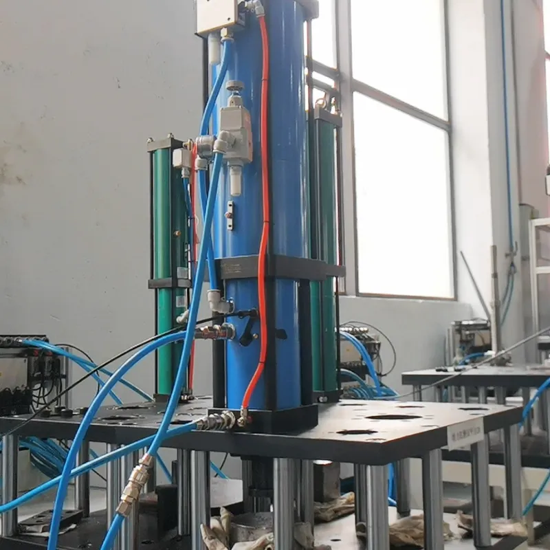
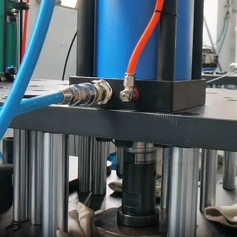
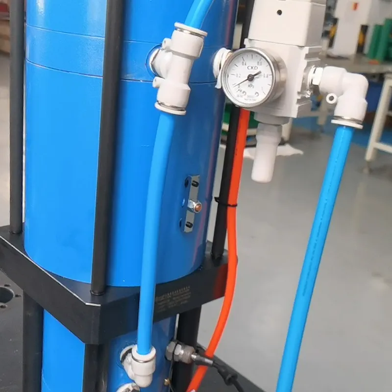
Configuration Diagram
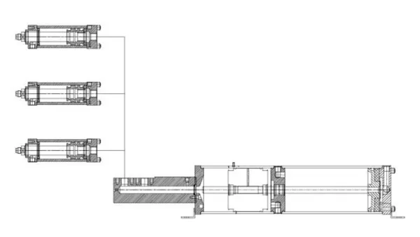
HZ Cylinder (Multiple Units) + HMPSxxx-xxx Intensifier
Cylinder Selection Example
- Requirement: 2 cylinders with 60kN force, 130mm stroke, 12mm pressure stroke, side-exit oil port, synchronous action, oil pipe length 1200mm, with an intensifier option.
- The HZ07 cylinder provides a maximum output of 76kN at an oil pressure of 250 bar, which meets the application requirements. To drive this, the HMPS series intensifier is selected, which utilizes 6 bar air pressure to generate a maximum hydraulic output of 250 bar.
- A1 (Cylinder Stroke): Since the required stroke is 130mm, a standard 150mm stroke is selected.
Total volume for 2 cylinders = 2×150 ×3.1CC×1.5 (Safety storage coefficient) = 1395CC - A2 (Volume Loss Due to Hose Length) = (1200/50)×3.1CC (V1) = 74.4CC
- A0 (Total Required Low-Pressure Oil): 1395CC+74.4CC = 1469.4CC
- B1 (Cylinder Consumption): Volume for 2 cylinders = 2×12×3.1CC (V) = 74.4 CC.
- B2 (Volume Loss Due to High-Pressure Hose Expansion) = 2×(1200/100)×0.6 CC (V2) = 14.4 CC.
- B0 (Total Required High-Pressure Oil): 74.4 CC + 14.4 CC = 88.8 CC.
- Final Selection Result
Working Cylinders: HZ07-150-02 (Quantity: 2 units)
Drive Intensifier: HMPS160.100.134 (Quantity: 1 unit)
High-Pressure Hoses: LH06-1200 (Quantity: 2 units)
Applicable Processes
 Forming
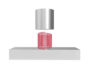 Testing
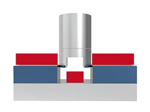 Stamping
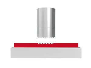 Embossing
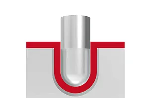 Drawing
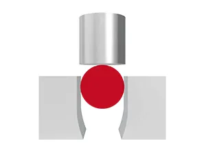 Sealing
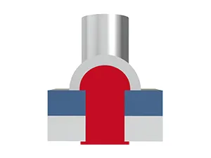 Riveting
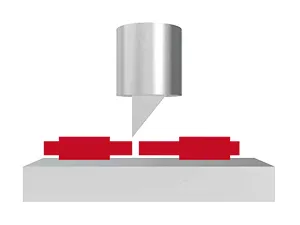 Cutting
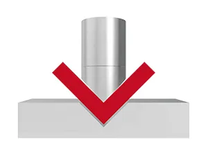 Bending
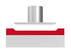 Compression
 Clinching
 Press fitting