
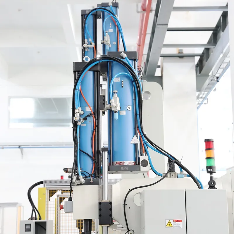


Pneumohydraulic Cylinder, BS Series
- Pressing force 2-2000kN
- Force stroke 6-52mm
- Total stroke 100/200mm
The pneumohydraulic cylinder, or pneumohydraulic intensifier cylinder is a drive unit that combines the high speed of pneumatic actuation with the high output force of hydraulic systems. It operates with a rapid pneumatic approach to the workpiece, followed by hydraulic pressure generation in the final stroke to deliver high force. This design ensures precise and powerful pressing while maintaining high operating speed. With high energy efficiency and flexible control, it is widely used in stamping, clinching, assembly operations, and pneumatic-hydraulic press applications where both speed and high force are required.
| Model | Pressing force at 6 bar (kN) | Approach force at 6bar (kg) | Return force at 6bar (kg) | Pressure ratio | Max. oil pressure at 6bar (bar) |
| 11 | 95 | 105 | 62 | 345 | |
| 17 | 150 | 170 | 64 | 350 | |
| 35 | 240 | 260 | 69 | 380 | |
| 72 | 350 | 370 | 61 | 340 | |
| 135 | 500 | 700 | 64 | 350 | |
| 200 | 580 | 780 | 64 | 350 | |
| 276 | 730 | 1000 | 64 | 350 | |
| 476 | 1150 | 1700 | 61 | 340 | |
| 736 | 2355 | 3780 | 51 | 280 | |
| 970 | 2355 | 3780 | 69 | 380 |
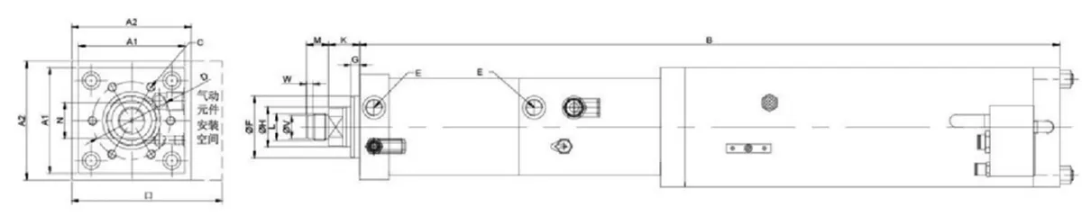
| Model | A1 | A2 | B | C | D | E | F(f7) | G | H | K | L | M | N | O | U(g6) | V | Remarks |
| 66 | 80 | 596 | 6-M6×12 | 40 | G1/8 | 30 | 10 | 16 | 24 | M12×1.5 | 15 | 13 | 110 | Spring | |||
| 66 | 80 | 786 | 6-M6×12 | 40 | G1/8 | 30 | 10 | 16 | 24 | M12×1.5 | 15 | 13 | 110 | Spring | |||
| 66 | 92 | 668 | 6-M6×12 | 40 | G1/8 | 30 | 10 | 16 | 24 | M12×1.5 | 15 | 13 | 135 | Spring | |||
| 66 | 92 | 868 | 6-M6×12 | 40 | G1/8 | 30 | 10 | 16 | 24 | M12×1.5 | 15 | 13 | 135 | Spring | |||
| 78 | 92 | 683 | 6-M08×15 | 54 | G1/4 | 40 | 10 | 20 | 26 | M16×1.5 | 15 | 17 | 135 | Spring | |||
| 78 | 92 | 883 | 6-M08×15 | 54 | G1/4 | 40 | 10 | 20 | 26 | M16×1.5 | 15 | 17 | 135 | Spring | |||
| 78 | 112 | 714 | 6-M08×15 | 54 | G1/4 | 40 | 10 | 20 | 26 | M16×1.5 | 15 | 17 | 150 | Spring | |||
| 78 | 112 | 914 | 6-M08×15 | 54 | G1/4 | 40 | 10 | 20 | 26 | M16×1.5 | 15 | 17 | 150 | Spring | |||
| 98 | 112 | 730 | 6-M08×18 | 64 | G3/8 | 50 | 10 | 30 | 29 | M22×2 | 20 | 24 | 150 | 18 | 7 | Spring | |
| 98 | 112 | 937 | 6-M08×18 | 64 | G3/8 | 50 | 10 | 30 | 29 | M22×2 | 20 | 24 | 150 | Spring | |||
| 98 | 137 | 762 | 6-M08×18 | 64 | G3/8 | 50 | 10 | 30 | 29 | M22×2 | 20 | 24 | 180 | 18 | 7 | Spring | |
| 98 | 137 | 962 | 6-M08×18 | 64 | G3/8 | 50 | 10 | 30 | 29 | M22×2 | 20 | 24 | 180 | Spring | |||
| 120 | 137 | 792 | 6-M10×20 | 88 | G1/2 | 70 | 10 | 45 | 35 | M30×2 | 25 | 36 | 180 | 26 | 7 | Spring | |
| 120 | 137 | 1008 | 6-M10×20 | 88 | G1/2 | 70 | 10 | 45 | 35 | M30×2 | 25 | 36 | 180 | 26 | 7 | Spring |
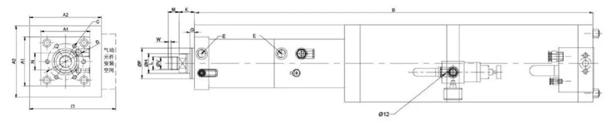
| Model | A1 | A2 | B | C | D | E | F (f7) | G | H | K | L | M | N | O | Remarks |
| BS08-100-24A | 120 | 177 | 872 | 6-M10×20 | 88 | G1/2 | 70 | 10 | 45 | 35 | M30×2 | 25 | 36 | 220 | Gas Spring |
| BS08-200-24A | 120 | 177 | 1072 | 6-M10×20 | 88 | G1/2 | 70 | 10 | 45 | 35 | M30×2 | 25 | 36 | 220 | Gas Spring |
| BS15-150-12A | 145 | 177 | 1044 | 6-M16×25 | 100 | G1/2 | 75 | 15 | 50 | 36 | M30×2 | 25 | 41 | 220 | Gas Spring |
| BS15-250-12A | 145 | 177 | 1300 | 6-M16×25 | 100 | G1/2 | 75 | 15 | 50 | 36 | M30×2 | 25 | 41 | 220 | Gas Spring |
| BS15-150-24A | 145 | 216 | 1114 | 6-M16×25 | 100 | G1/2 | 75 | 15 | 50 | 36 | M30×2 | 25 | 41 | 270 | Gas Spring |
| BS15-250-24A | 145 | 216 | 1314 | 6-M16×25 | 100 | G1/2 | 75 | 15 | 50 | 36 | M30×2 | 25 | 41 | 270 | Gas Spring |
| BS20-150-12A | 166 | 177 | 1110 | 6-M20×30 | 115 | G1/2 | 85 | 18 | 56 | 52 | M39×2 | 35 | 46 | 220 | Gas Spring |
| BS20-250-12A | 166 | 216 | 1359 | 6-M20×30 | 115 | G1/2 | 85 | 18 | 56 | 52 | M39×2 | 35 | 46 | 270 | Gas Spring |
| BS30-150-12A | 190 | 216 | 1135 | 6-M20×30 | 132 | G3/4 | 100 | 18 | 63 | 47 | M39×2 | 35 | 55 | 270 | Gas Spring |
| BS30-250-12A | 190 | 216 | 1385 | 6-M20×30 | 132 | G3/4 | 100 | 18 | 63 | 47 | M39×2 | 35 | 55 | 270 | Gas Spring |
| BS50-200-12A | 190 | 268 | 1285 | 8-M20×35 | 150 | G3/4 | 115 | 25 | 63 | 56 | M42×2 | 40 | 55 | 330 | Gas Spring |
| BS75-200-12A | 315 | 1629 | 12-M24×45 | 200 | G1 | 150 | 20 | 100 | 60 | M64×2 | 60 | 85 | 380 | Gas Spring | |
| BS100-200-12A | 315 | 332 | 1643 | 12-M24×45 | 200 | G1 | 150 | 20 | 100 | 60 | M64×2 | 60 | 85 | 380 | Gas Spring |
High efficiency and energy saving
The approach speed is faster than hydraulic systems and more stable than pure pneumatic systems. Rapid advance occurs in the pre-load stage, while high pressure output is delivered only during the intensification stage. Energy consumption is low, typically only 10-30% of conventional hydraulic systems, with no continuously running motor required.
Stable and controllable output force
A wide force range from 1-200t achieves output levels comparable to hydraulic presses. The soft-touch approach technology allows tooling to contact the workpiece smoothly, reducing impact, noise, and extending tool life.
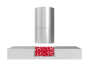 Forming
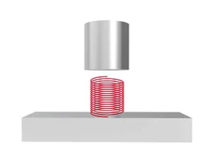 Testing
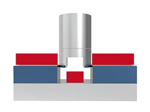 Stamping
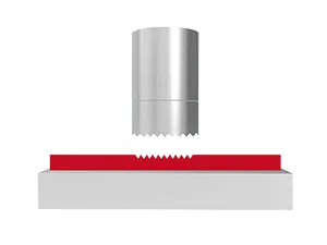 Embossing
 Drawing
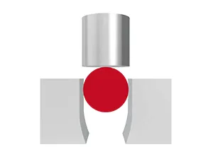 Sealing
 Riveting
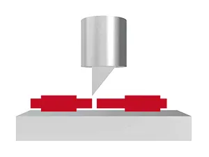 Cutting
 Bending
 Compression
 Clinching
 Press fitting