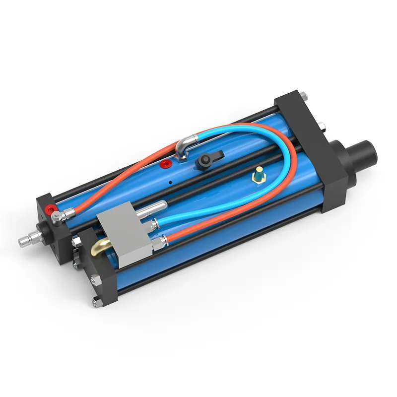
Pneumohydraulic Cylinder, BT Series
- Operating pressure ≤6bar
- Pressing force 2-2000kN
- Force stroke 5-52mm
- Total stroke 100/200/250mm
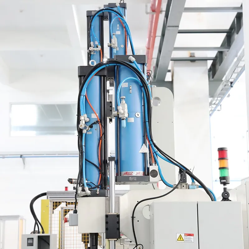
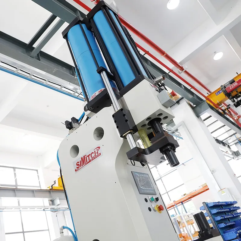
The pneumohydraulic cylinder drive unit combines the high-speed motion of pneumatic actuation with the high output force of hydraulic systems. A pneumatic cylinder provides rapid approach to the workpiece, while hydraulic components generate powerful and precise pressure during the final stroke. With high energy efficiency and flexible control, this solution reduces energy consumption while meeting industrial requirements for both speed and force, making it an ideal choice for pneumohydraulic presses and related equipment.
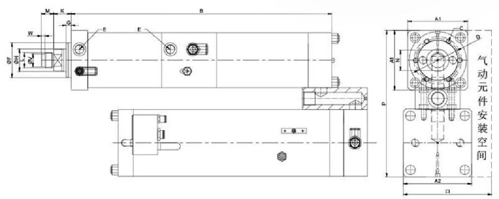
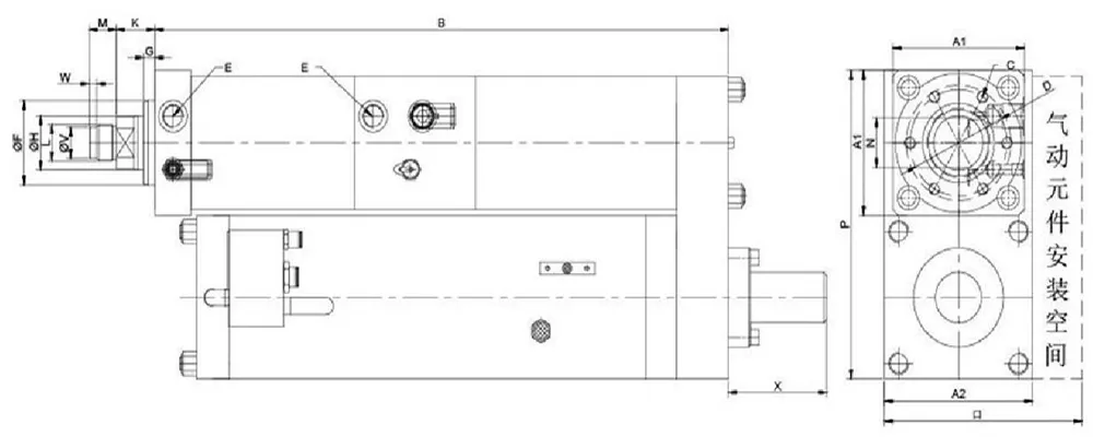
BT Series Dimensions
| Model | A1 | A2 | B | C | D | E | F (f7) | G | H | K | L | M | N | O | P | X | Remarks |
| 66 | 80 | 514 | 6-M6×12 | 40 | G1 /8 | 30 | 10 | 16 | 24 | M12×1.5 | 15 | 13 | 110 | 160 | 60 | Spring | |
| 66 | 92 | 514 | 6-M6×12 | 40 | G1/8 | 30 | 10 | 16 | 24 | M12×1.5 | 15 | 13 | 135 | 162 | 100 | Spring | |
| 78 | 92 | 529 | 6-M08×15 | 54 | G1/4 | 40 | 10 | 20 | 26 | M16×1.5 | 15 | 17 | 135 | 176 | 60 | Spring | |
| 78 | 112 | 529 | 6-M08×15 | 54 | G1/4 | 40 | 10 | 20 | 26 | M16×1.5 | 15 | 17 | 150 | 193 | 100 | Spring | |
| 98 | 112 | 551 | 6-M08×18 | 64 | G3/8 | 50 | 10 | 30 | 29 | M22×2 | 20 | 24 | 150 | 210 | 100 | Spring | |
| 98 | 112 | 751 | 6-M08×18 | 64 | G3/8 | 50 | 10 | 30 | 29 | M22×2 | 20 | 24 | 150 | 210 | 100 | Spring | |
| 98 | 137 | 551 | 6-M08×18 | 64 | G3/8 | 50 | 10 | 30 | 29 | M22×2 | 20 | 24 | 180 | 235 | 100 | Spring | |
| 98 | 137 | 751 | 6-M08×18 | 64 | G3/8 | 50 | 10 | 30 | 29 | M22×2 | 20 | 24 | 180 | 235 | 100 | Spring | |
| 120 | 137 | 585 | 6-M10×20 | 88 | G1/2 | 70 | 10 | 45 | 35 | M30×2 | 25 | 36 | 180 | 260 | 100 | Spring | |
| 120 | 137 | 791 | 6-M10×20 | 88 | G1/2 | 70 | 10 | 45 | 35 | M30×2 | 25 | 36 | 180 | 301 | Gas spring | ||
| 145 | 177 | 713 | 6-M16×25 | 100 | G1/2 | 75 | 15 | 50 | 36 | M30×2 | 25 | 41 | 220 | 366 | Gas spring | ||
| 145 | 216 | 713 | 6-M16×25 | 100 | G1/2 | 75 | 15 | 50 | 36 | M30×2 | 25 | 41 | 270 | 405 | Gas spring | ||
| 166 | 216 | 726 | 6-M20×30 | 115 | G1/2 | 85 | 18 | 56 | 52 | M39×2 | 35 | 46 | 270 | 426 | Gas spring | ||
| 190 | 216 | 740 | 6-M20×30 | 132 | G3/4 | 100 | 18 | 63 | 47 | M39×2 | 35 | 55 | 270 | 452 | Gas spring | ||
| 190 | 268 | 771 | 8-M20×35 | 150 | G3/4 | 115 | 25 | 63 | 56 | M42×2 | 40 | 55 | 330 | 574 | Gas spring | ||
| 315 | 332 | 864 | 12-M24×45 | 200 | G1 | 150 | 20 | 100 | 60 | M64×2 | 60 | 85 | 380 | 722 | Gas spring | ||
| 315 | 332 | 864 | 12-M24×45 | 200 | G1 | 150 | 20 | 100 | 60 | M64×2 | 60 | 85 | 380 | 722 | Gas spring |
Applicable Processes
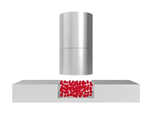 Forming
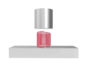 Testing
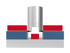 Stamping
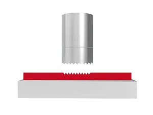 Embossing
 Drawing
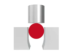 Sealing
 Riveting
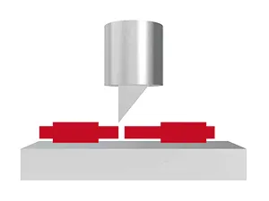 Cutting
 Bending
 Compression
 Clinching
 Press fitting